In a significant step forward for precision RF engineering and product innovation, Electro-Technical is proud to announce the launch of its cutting-edge electromagnetic (EM) simulation capabilities. This latest advancement empowers us to model and optimize electromagnetic behavior in customer designs—before a single prototype is built.
Whether you’re designing antennas, high-speed PCBs, or shielding systems, understanding how electromagnetic fields interact with your components is crucial. Our access to Ansys tools, including SiWave and HFSS offers an integrated solution for analyzing complex EM phenomena such as radiation, coupling, crosstalk, signal integrity, and electromagnetic interference (EMI).
As a simple case study, the following image shows a subsection of a PCB design for a 20 GHz amplifier IC. The amplifier IC requires a DC bias, supplied via a conical inductor (L4). RF signals travel via Grounded Co-planar Waveguide (GCPWG), with a tightly optimised geometry, however the footprint pads of the inductor represents a large change to this geometry, with the potential to create an impedance discontinuity, resulting in lossy performance.
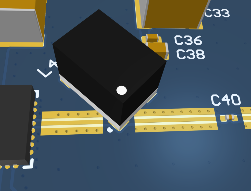
The large pad for the inductor is likely to present as increased capacitance in the transmission line, which is poor for signal integrity.
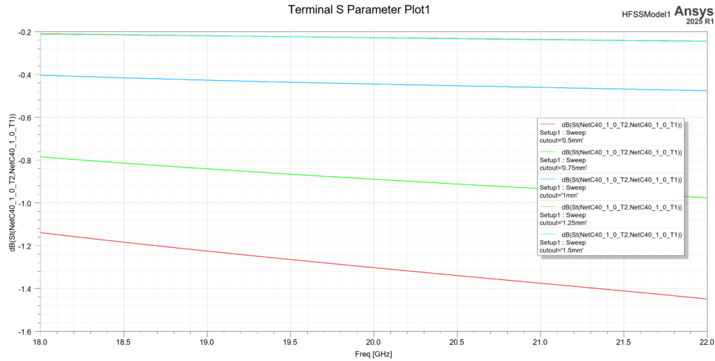
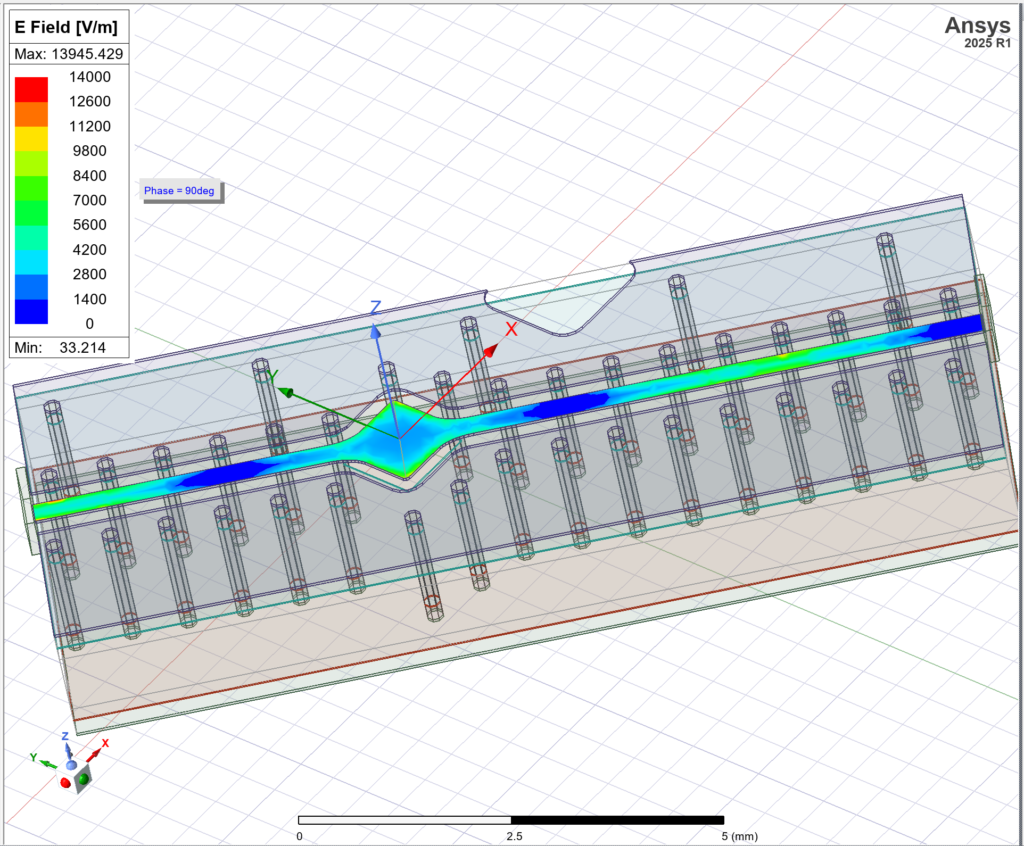
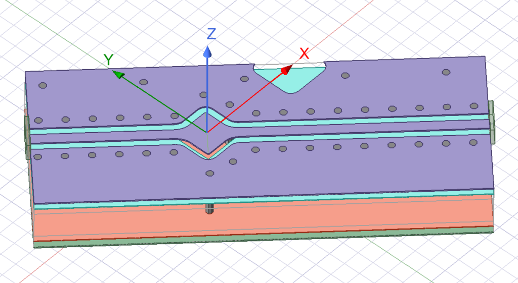
To optimise this, one option is to cut a section out of the ground plane immediately below the pad, reducing coupling to ground, and thus the capacitance presented by the large pad. The image below shows a portion of the design imported into HFSS, where a cutout has been made in the ground plane. The cutout geometry is controlled by local variables, so a set of simulations can be run to investigate what size cutout gives optimum signal levels at the output of the circuit.
The results clearly show that a square cutout of at least 1.25mm sides is required to optimise losses through these copper features in the band of interest 18 – 22 GHz. At the centre frequency of 20 GHz, this results in over 1 dB lower loss compared to a 0.5mm cutout, which is quite significant.